Story:
In autumn 2016, I bought this oscilloscope on ebay for 130
Euros. I was very tempted to get it, as the 545 oscilloscope
does not contain transistors, yet. It's all-tube technology. I
got very interested in starting to work with tube technology
during a repair weekend I did with Prof. Bernd Ulmann. There,
we tried to repair a Tektronix 547 oscilloscope, which uses a
mixture of tubes and transistors.
The seller of the 545 'scope was located nearby my place.
Thus, a pick-up was very convenient. This unit came with
a CA-plug-in and a special trolley which can hold two more
plug-ins. He told me that I got this oscilloscope from the
Physics Department of the Karlsruhe University of Technology
when the oscilloscope was decomissioned there in the early
1990's. He had the scope since then in his house, but never
used it. Additionally, he said that he made a small test by
turning it on, but the CRT beam became not visible. That meant
that I would have to repair it - challenge accepted ! :)
It follows a little blog of my repairing and restoration project that began in March 2017:
First, I connected the 'scope to a variac and ramped up the
voltage to 230 volts. I made to observations:
1. The CRT beam only became visible when
the trigger was set to "external trigger".
2. After 15 minutes, strange noises started
to appear. Probably one or more capacitors started to suffer
from the heat due to leakage-related issues.
It was time to get the service guide and verify the proper operation of the power supply circuit. I was impressed that it provides five different high voltages! First, the resistances for the five voltage rails need to be checked according to table 2.1 on page 37:
-150V to Gnd: 3kOhm or more: 3.2kOhm: ok
+100V to Gnd: 5KOhm or more: 10.9kOh: ok
225V to Gnd: 5KOhm or more: 5kOhm: ok
+350V to Gnd: 10KOhm or more: 18kOhm ok
+500V to Gnd: 25KOhm or more: 38kOhm: ok
Important is to not forget to insert a plug-in as when
measuring the resistance of the 100V-Gnd rail, as stated in
the service guide. This supply rail is amongst others used for
the plug-ins! I forgot to plug the plug-in back into the
'scope and was fooling around for quite a while before
realizing that the plug-in had to be in!
The next step was to test the relay which went well. Here, a
dual-trace plug-in unit is needed and I was happy that it was
part of the plug-ins that came with the oscilloscope.
Next, I measured the supply voltages with a voltmeter at a
position at the bottom of the 'scope as advised by the service
guide. The voltages are required to be within a tolerance of
2%.
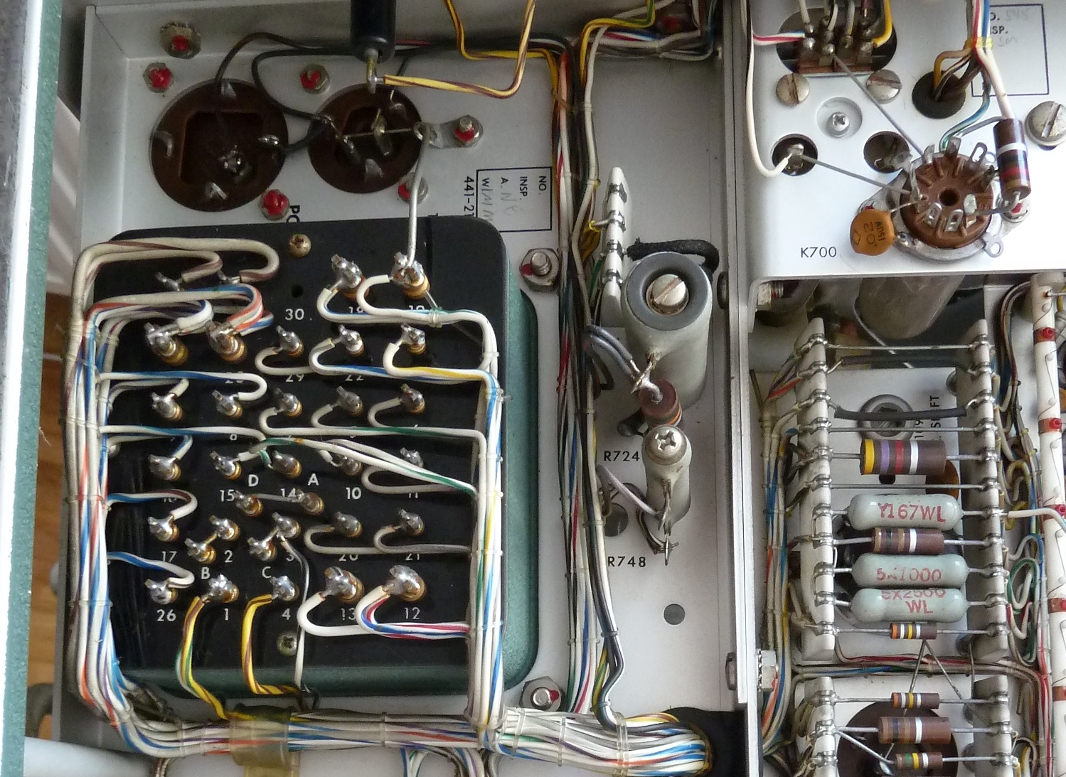
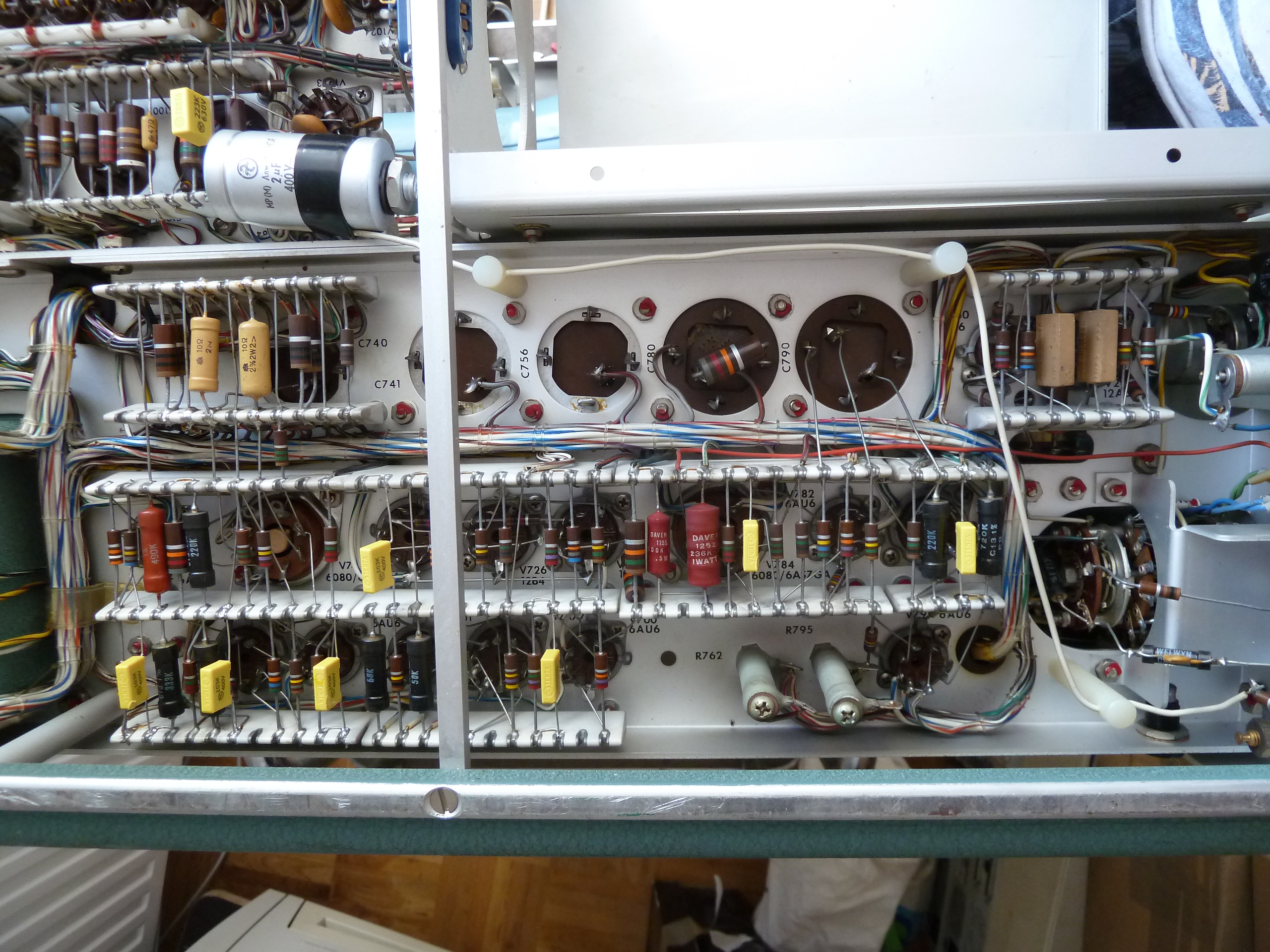
The five voltages can be measured at the lines that are between the resistors (right side of picture).
|
Voltage rail: |
-150V |
+100V |
+225V |
+350V |
+500V |
|
Measured voltage: |
-148V -> ok |
96.2V -> too low |
172 -> too low |
362 -> too high |
510V -> ok |
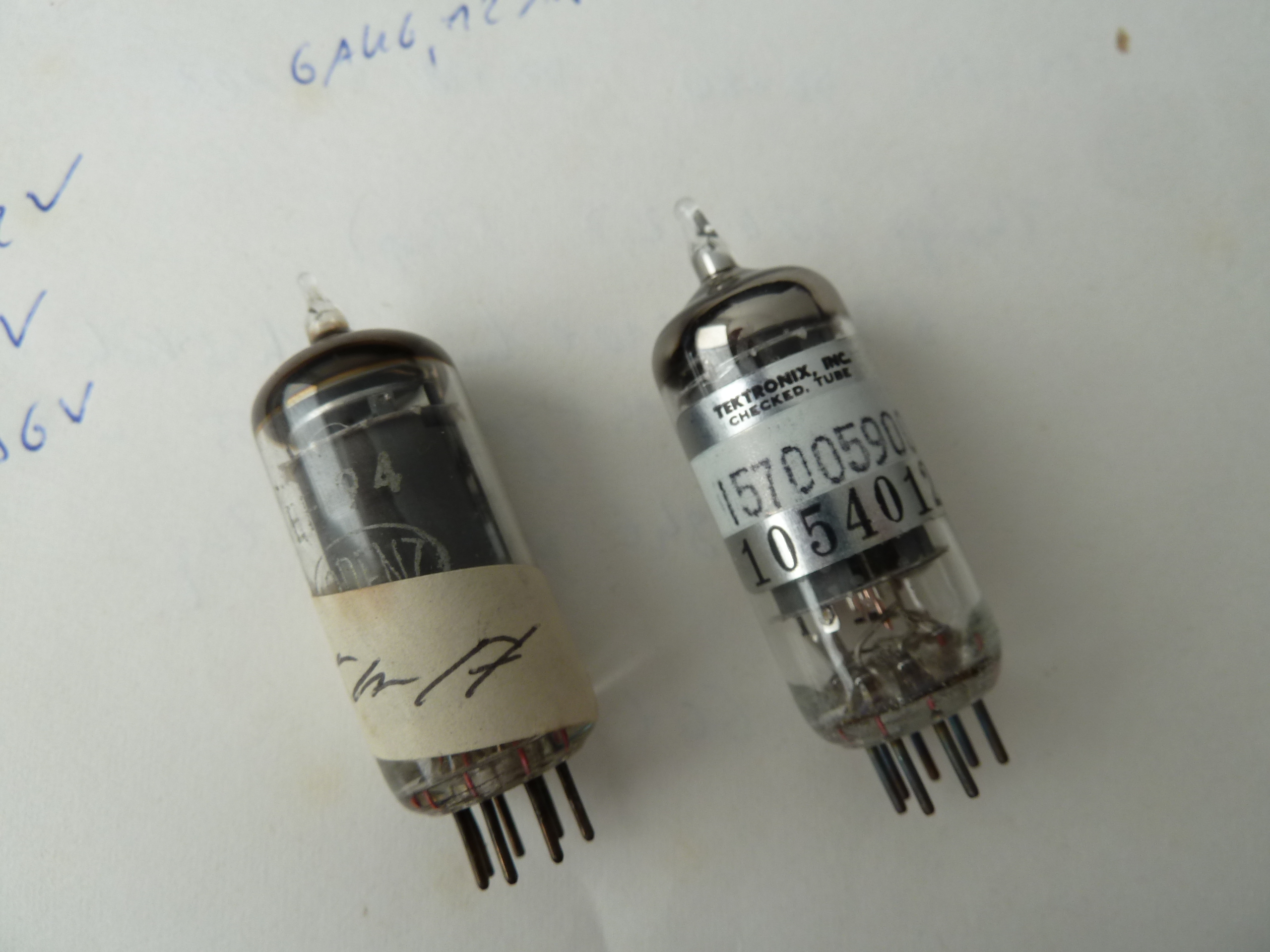
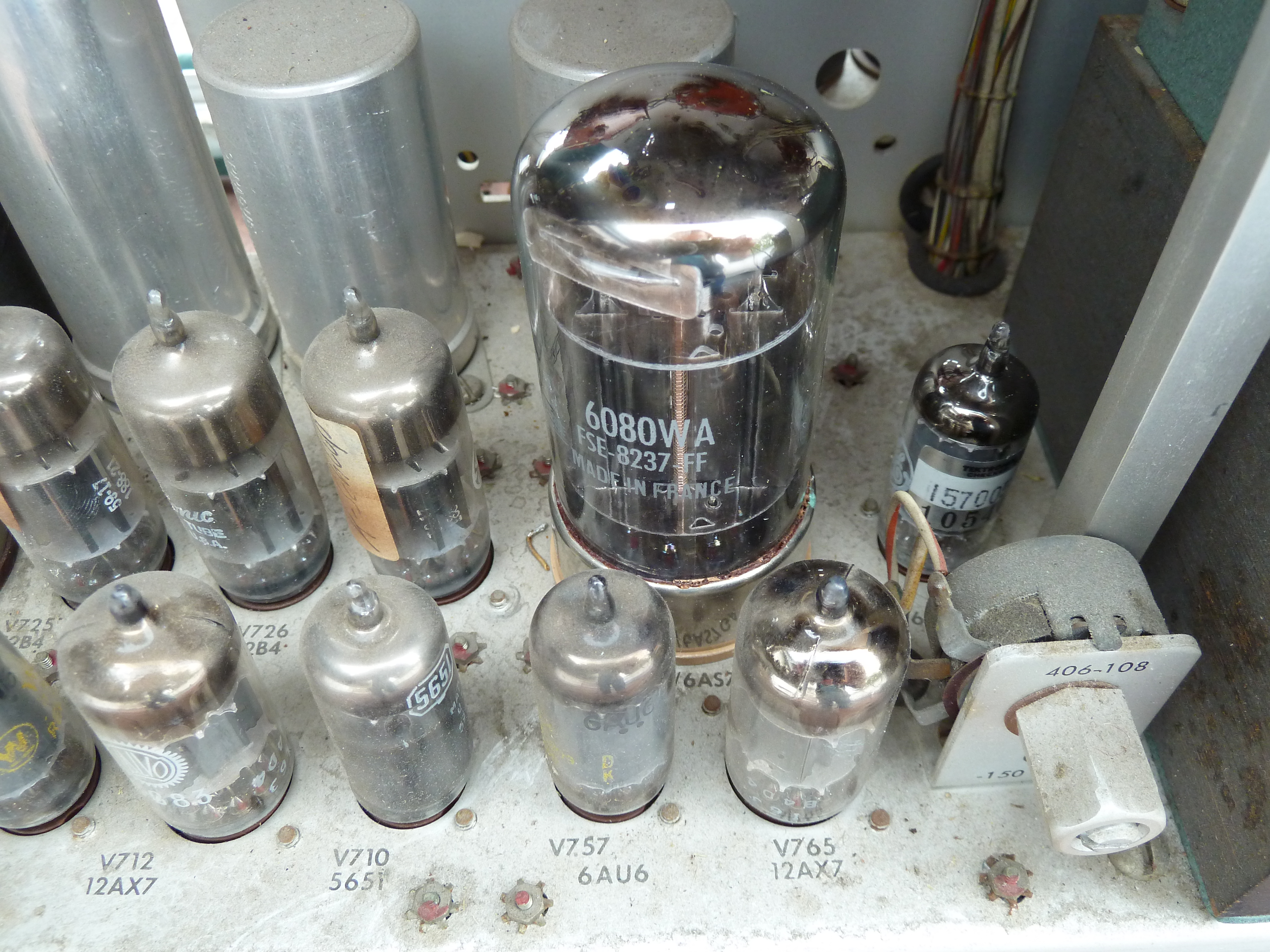
The 500V rail is the result of inverting and adding the 150V rail to the 350V rail. Three voltage rails had voltages that were not within the required tolerance. In case of the 225V rail being too low, the service guide recommended to change the tube V748 (of type 6080) and to check the 0.01uF capacitors C763 and C770. First, I had to get spare tubes! So I checked ebay and got a Thomson new-old-stock (NOS) replacement tube. The replacement led to the +225V rail being in the required tolerance! The +100V and +350V rails still were out of tolerance, though. In that case, the tube V742 was to verify. The service guide recommended to check for that tube of type 6AU6. Interestingly, this tube was probably changed in the past already, as there was a Lorenz EF94 tube seated in the V742 socket.
Again with the help of ebay, I bought some unused tubes from GE that were certified and tested by Tektronix (PN: 157005900)! Replacing V742 helped to bring the two voltages back into the required tolerance range.
Below is the summary of the measured voltages.
|
Voltage rail: |
-150V |
+100V |
+225V |
+350V |
+500V |
|
Initial measurement: |
-148V -> ok |
96.2V -> too low |
172V ->too low |
362V -> too high |
510V -> ok |
|
after V748
change: |
-149.2V ->ok |
134.4V -> too high |
225.2V -> ok |
365V -> too high |
496V -> ok |
|
after V742 change: |
-149.4V -> ok |
99.5V -> ok |
225.4V -> ok |
347.2V -> ok |
496V -> ok |
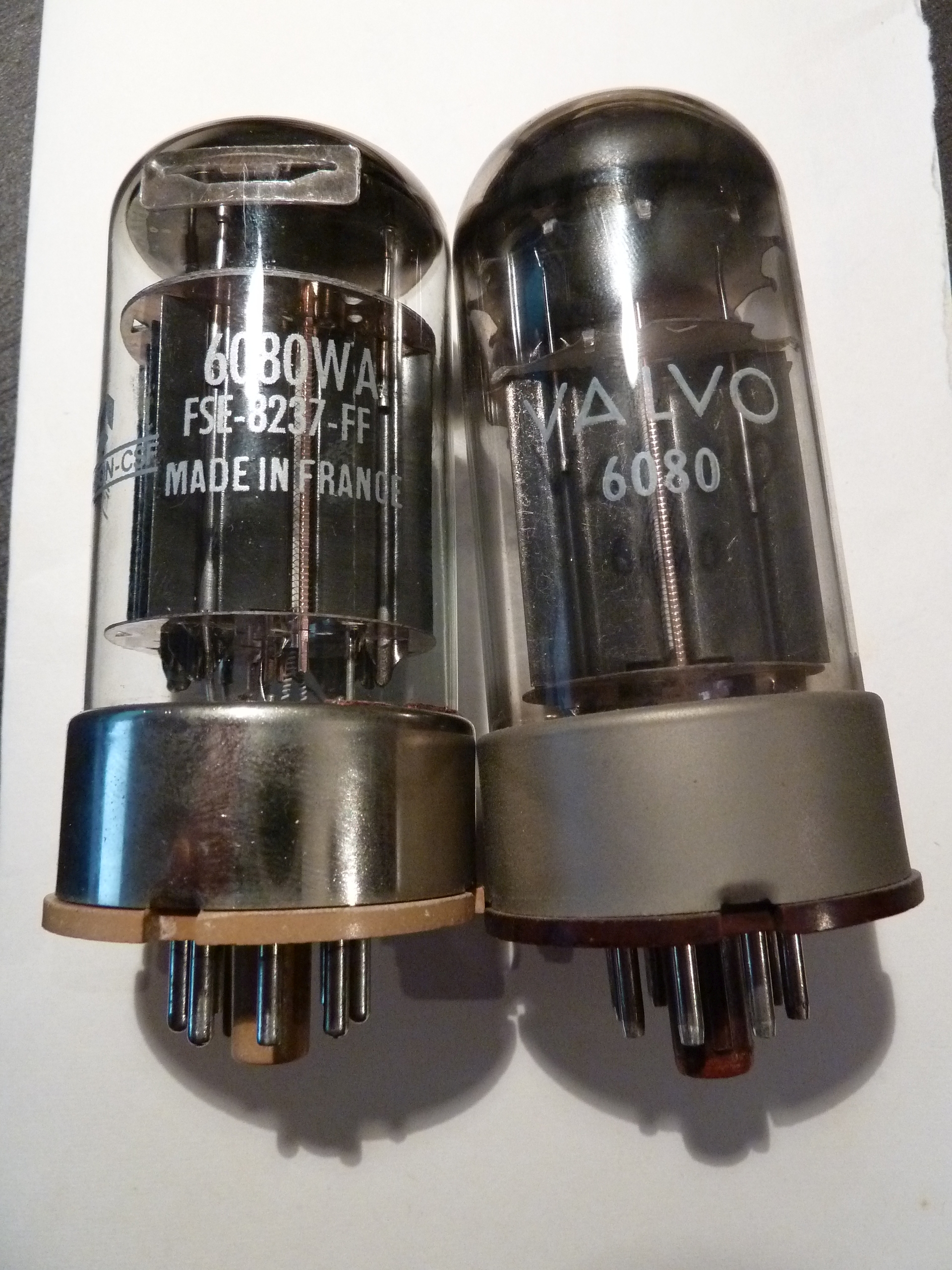
Left tube: Thomson Replacement, right tube: defective Valvo tube.
Resistor replacement:
While carefully doing a visual inspection of the components, I stepped over the resistor shown in the picture below:
During desoldering, it turned out that it was broken in two
halves! As the color code was not visible anymore, I tracked
the resistor down in the schematics (R1007) and replaced it.
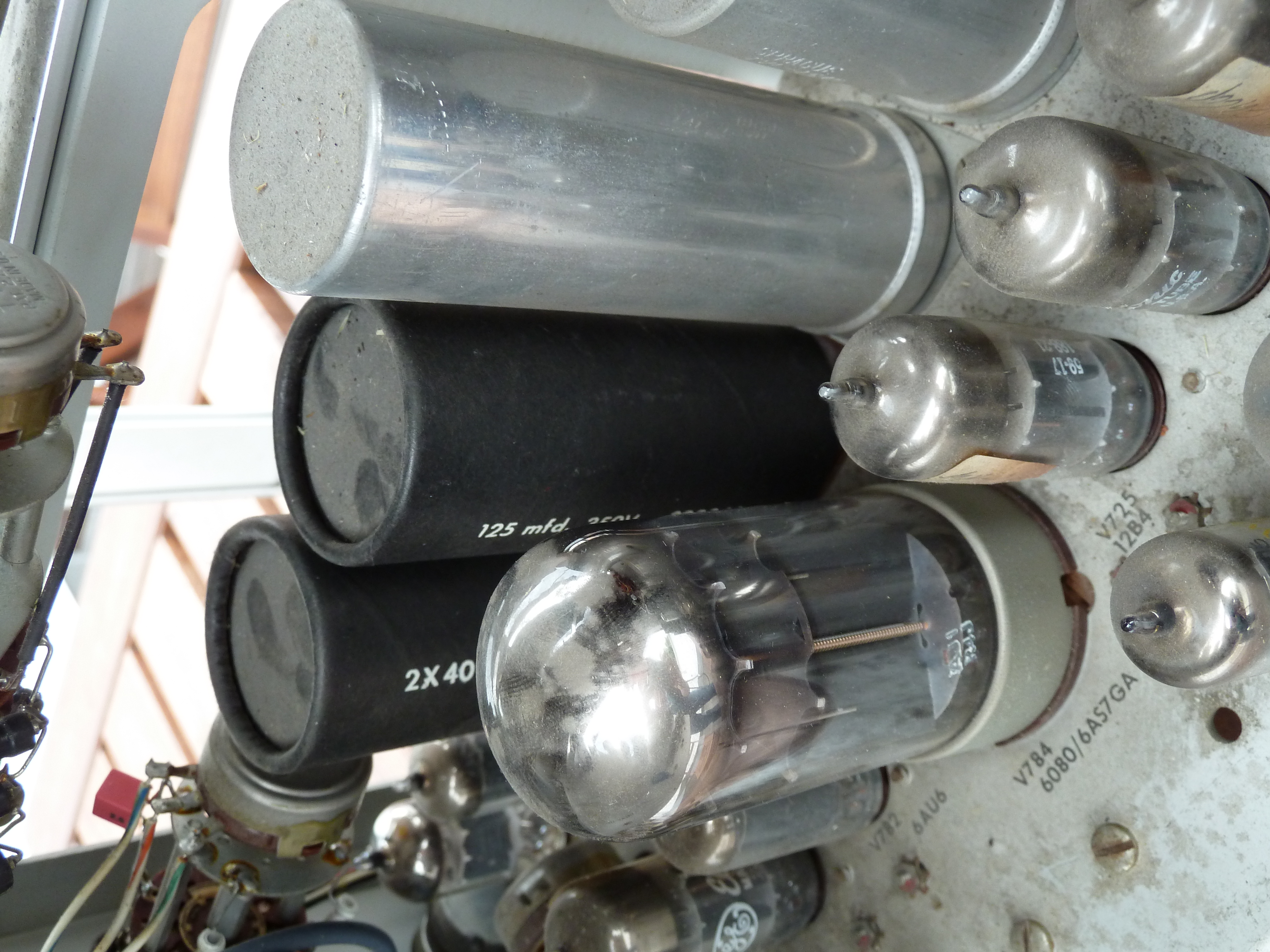
Capacitor replacements:
While reading experiences done with other Tektronix
500-series restoration projects, there were contradictory
statements and discussions related to paper-tape-based
capacitors from the 1950s. They seem to become "leaky" over
time and some people wrote that it would be best to replace
them all. Others state that they did not experience issues
with this capacitor type. These capacitors seem to be known as
"Black Beauties" or "Bumblebees". As I was in the processing
of repairing & restauring the scope, I decided to replace
them all except for a few high-voltage capacitors. Regarding
the latter, the problem was that I could not locate a supplier
that sells these per piece, they usually are sold at minimum
amounts of 500 pieces or more.
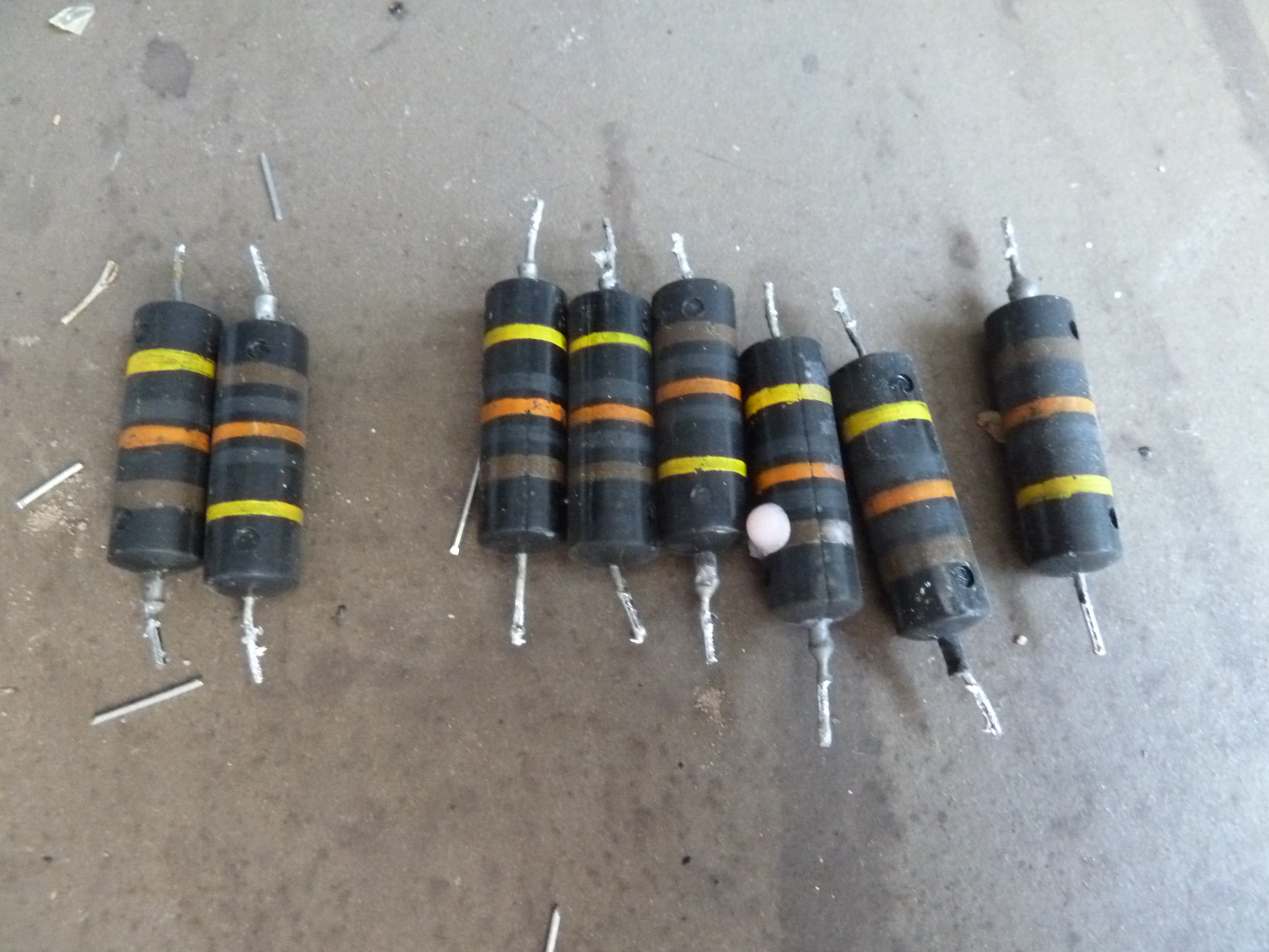
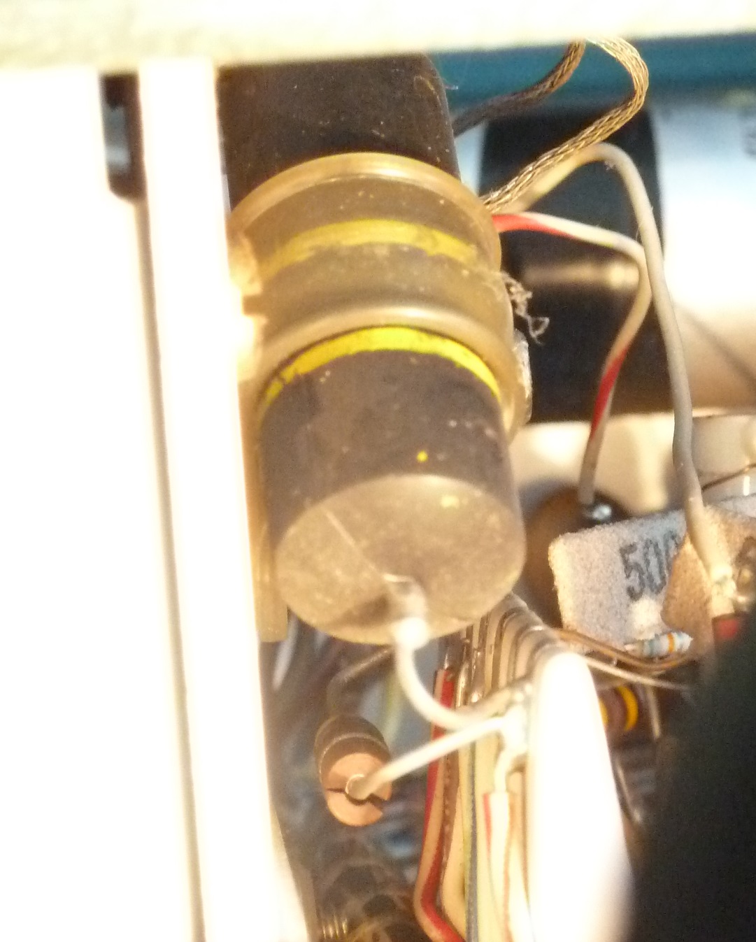
Desoldered paper-tape-based
capacitors
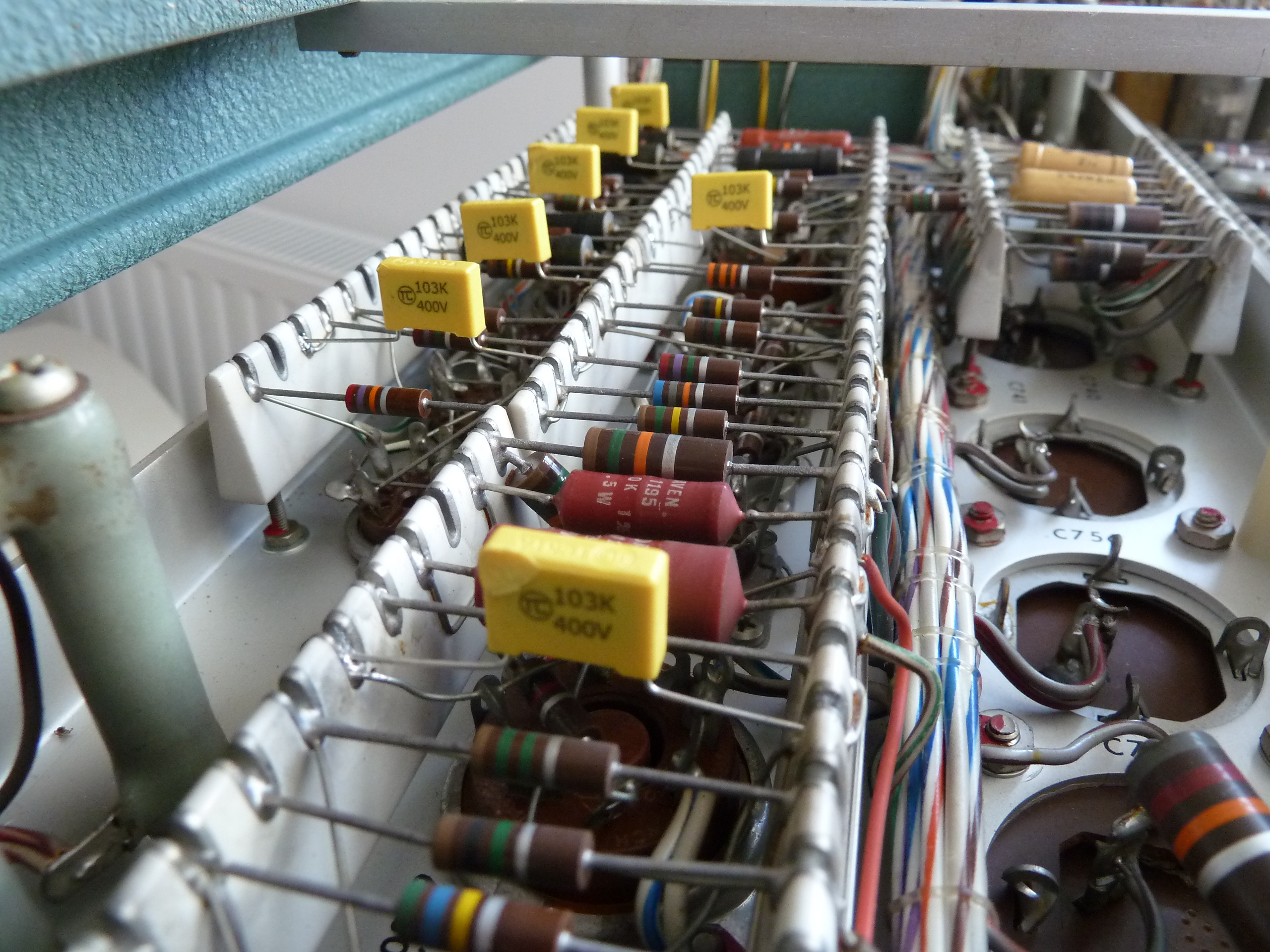
The yellow-collored capacitors are the new ones.
capacitance the old one had.
The three caps were mounted on the aluminium socket of the former capacitor and were covered by the original black paper cover so that the transformation using new components is kept secret :) This preserves the original look of the capacitor section. The work required was one and a half hours to get this done - and it's totally worth!
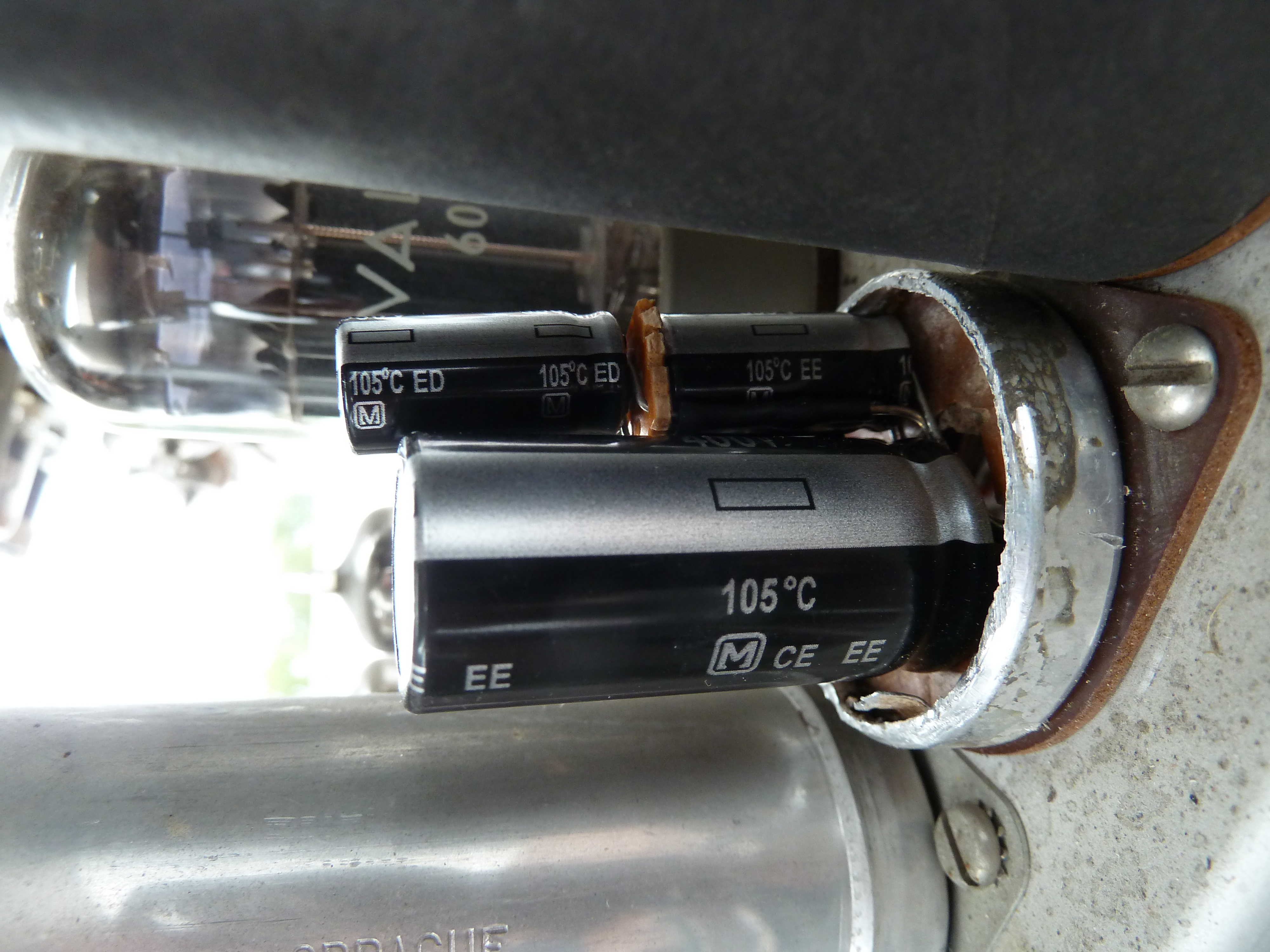
The two smaller caps had to be stacked to make everything fit into the socket of the former capacitor.
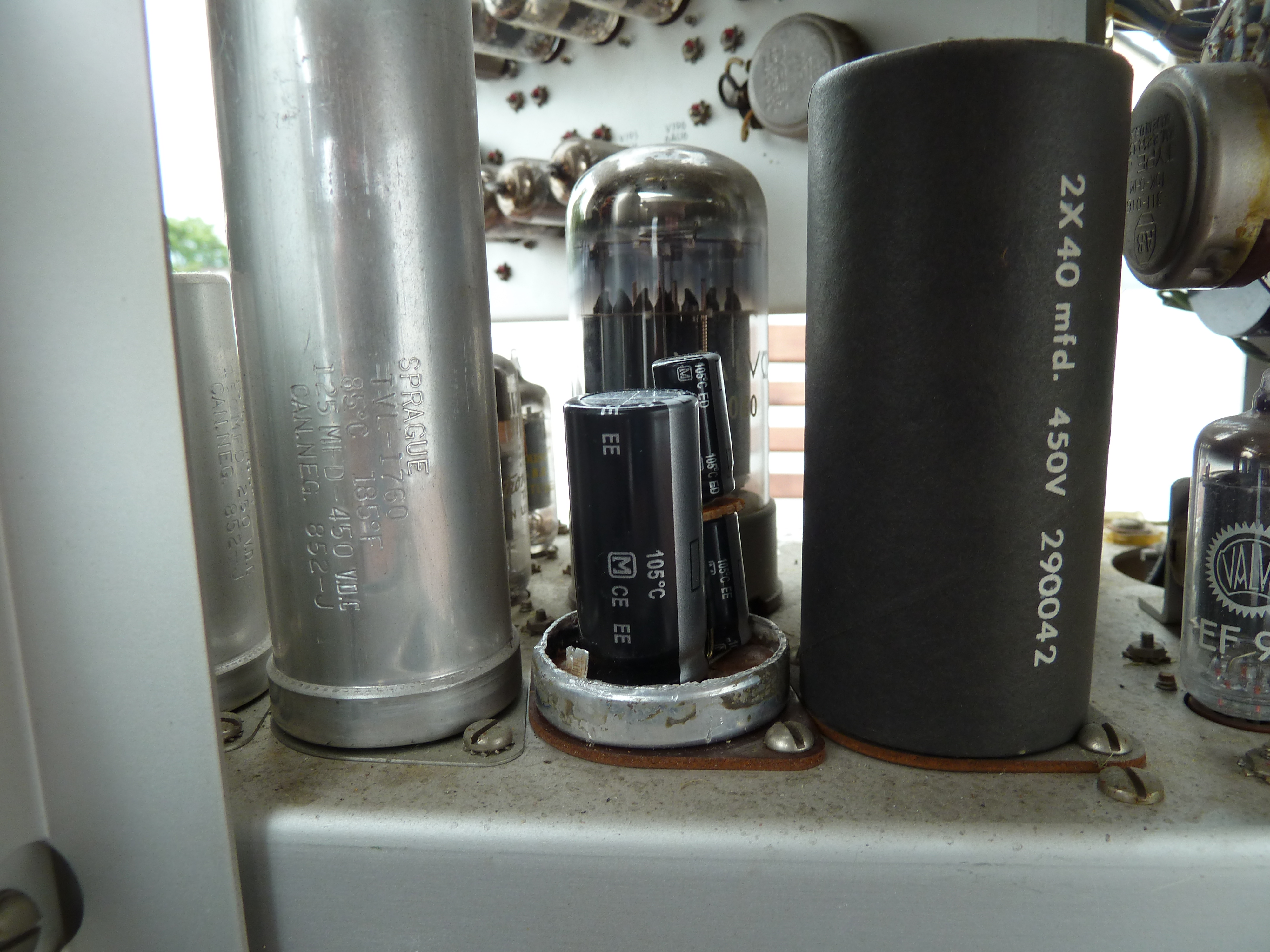
Nice comparison of the sizes between the cap technology from the 1950s and technology from the 2010s
Once the work was done, the black paper cover was slided back on the aluminium socket to preserve the original looks.
Then, I slowly brought up the mains voltage up to 230V using a variac and the main secondary voltages of the power supply were within expected tolerances as given in the manual.
I could thus proceed with the testing procedures as described by Tek.
The PSU output voltage ripples where checked using a working Tek 5403 oscilloscope and turned out to be within the specification.
As a next step, I decided to reajust the precision "-150V rail" to have it precisely set from -149.3V to -150.0V. Since all other output voltages are derived from that rail, I had to check all other voltages again:
|
nominal voltages |
-150V |
+100V |
+225V |
+350V |
+500V |
|
Voltage measured DC after readjustment |
-150.0V |
99.8V |
225.8V |
348.5V |
499V |
Following the course of actions described in the manual, I continued with a look at the function of the calibrator circuit which is supposed to deliver a rectangular signal at a fixed frequency. Here, the voltages were within the tolerances as stated in chap. 3 of the Tek service manual.
Chap. 4 deals with the high-voltage section of the oscilloscope. the task is verify, if the output voltage is around -1400V. Using a high-voltage probe Tektronix P6015 on the 5403 oscilloscope, I verified that the high voltages were within tolerance. Since very high voltages are implied, such works need to be done with particularly much precausion. Never do this in a hurry, double-check everything before starting with measurements!!!
Since the PSU high voltage outpus was fine, I continued with section 4.1.2 to verify the cathode supply regulation. The proper function can be visually checked by setting all scpoe settings according the the Tek guide. If things are in working order, a bright, defocused trace should appear. However, in my case, noting appeared on the tube!
According to the recommendations of Tek (chap. 4.1.4), it was then time to connect the calibrator output to one of the inputs of the plug-in that I got with the 545 scope. After playing a bit with the vertical and horizontal deflection settings, I figured out that the scope only showed a signal within the left half of the cathode ray tube. The vertical shifting and scaling, however, worked well.
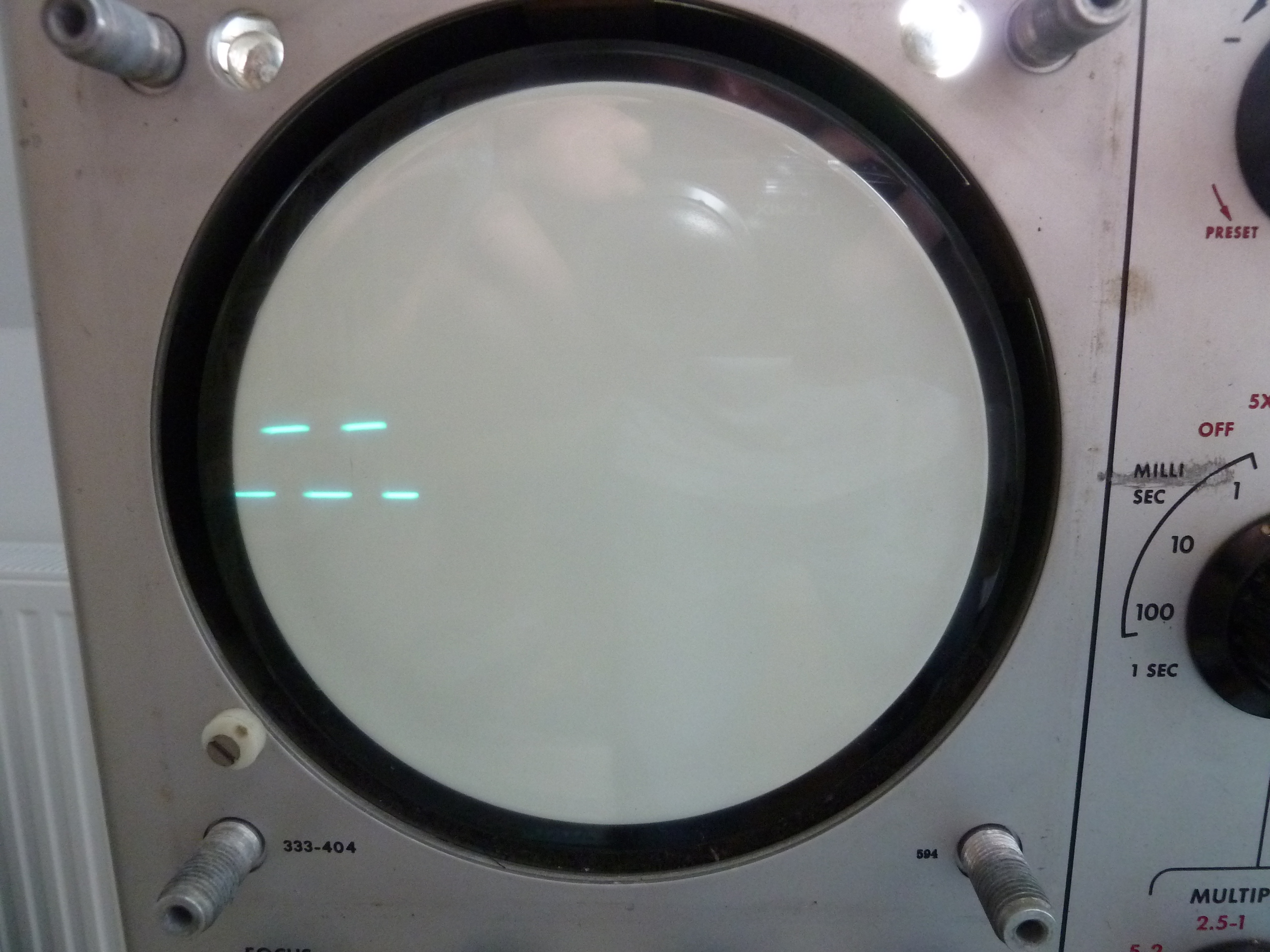
The calibration signal was only visible on the left side of the screen, no matter the horizontal deflection settings chosen.
In order to verify the voltages of the horizontal deflection plates, I followed a description in the service manual in chap. 5.1.2., where the external sweeping setting and the magnifier x5 should be set in order to only obtain a centered spot on the CRT.
The right plate's voltage was 180V whereas the left plate was at 164V, which were both far from 310V to GND as stated in the guide. Moreover, the horiztonal indicator lights do not behave as expected, when turning horizontal position to left and right. Set to right position, the right light indicator stayed off, while on left position, the left turned on while the right one remained on, too, which is not the expected behaviour.
These indicators are supposed to indicate to which side the beam is deflected when it's outside of the visible tube area.
So I started checking resistors and some caps within the sweep amplifier. The result was that one resistor was electrically broken in terms of an open circuit (no electrical connection between its terminals) and two further resistors were far out regarding their their allowed resistance tolerances.
The resistors were the following ones:
- R286 (mita plate, 6k & 30k resistors, 5W, +1% tolerance) open regarding 30kOhm terminal
- R267 (2.2kOhm, 1W, 10%) measures a very low value of 1.4kOhm -> out of spec
- R292(470kOhm, 0.5W, 10%) measures low value of 390kOhm -> out of spec
The Mita plate type resistor is a specially made one with very low tolerance and integrates two resistors of which the 30kOhm section is "open". Here, I decided to leave the component in place regarding the 6kOhm section and replace the 30kOhm resistance by ordering two 15k resistors with low tolerance and solder them in series.

On the front: The rectangular Mita plate-type resistor, which seems to be a custom component with non-typical resistor values and low tolerances.
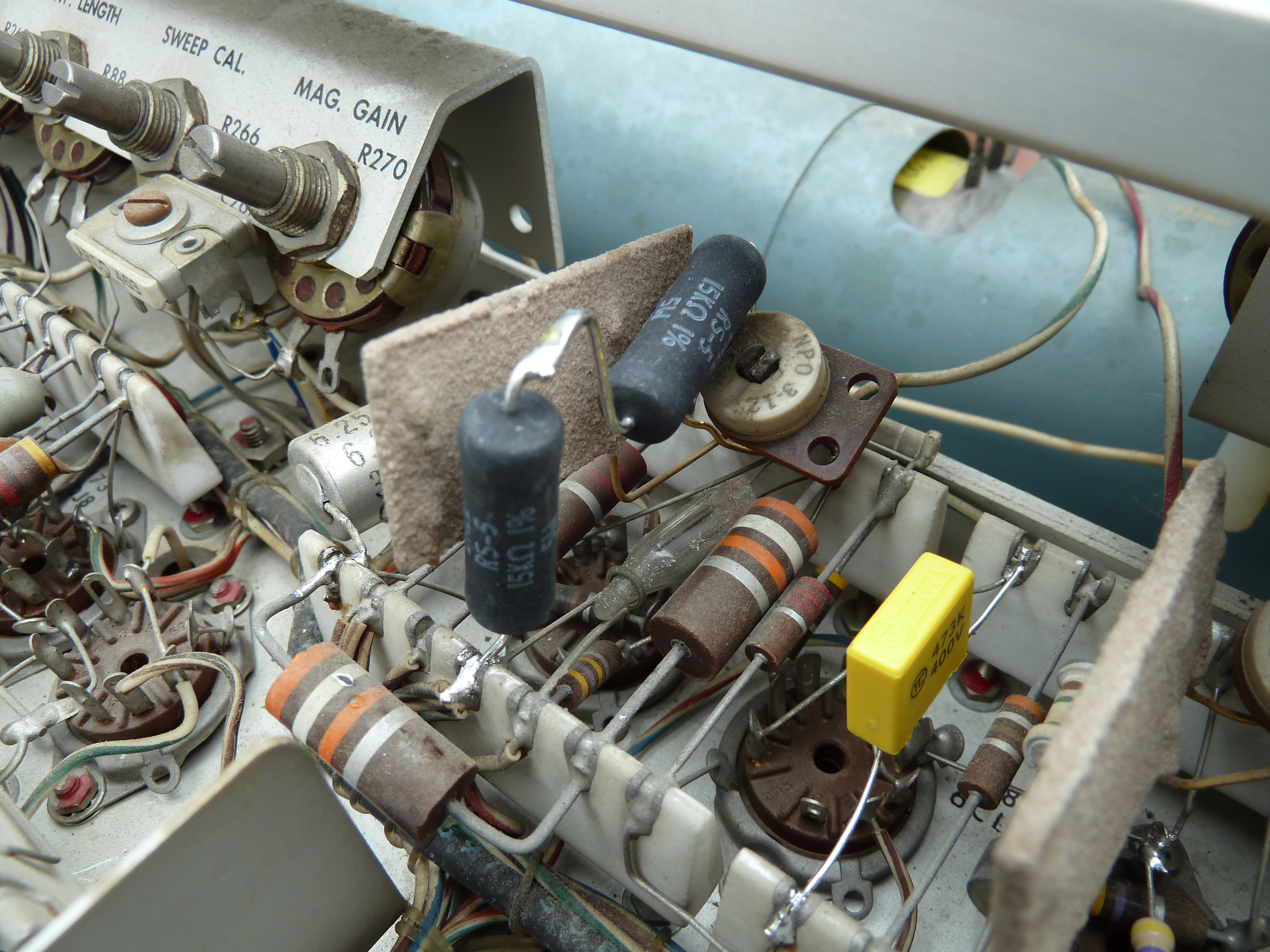
Close to the the rectangular Mita plate-type resistor are located two new black resistors that replace the 30KOhm section broken in that plate resistor.
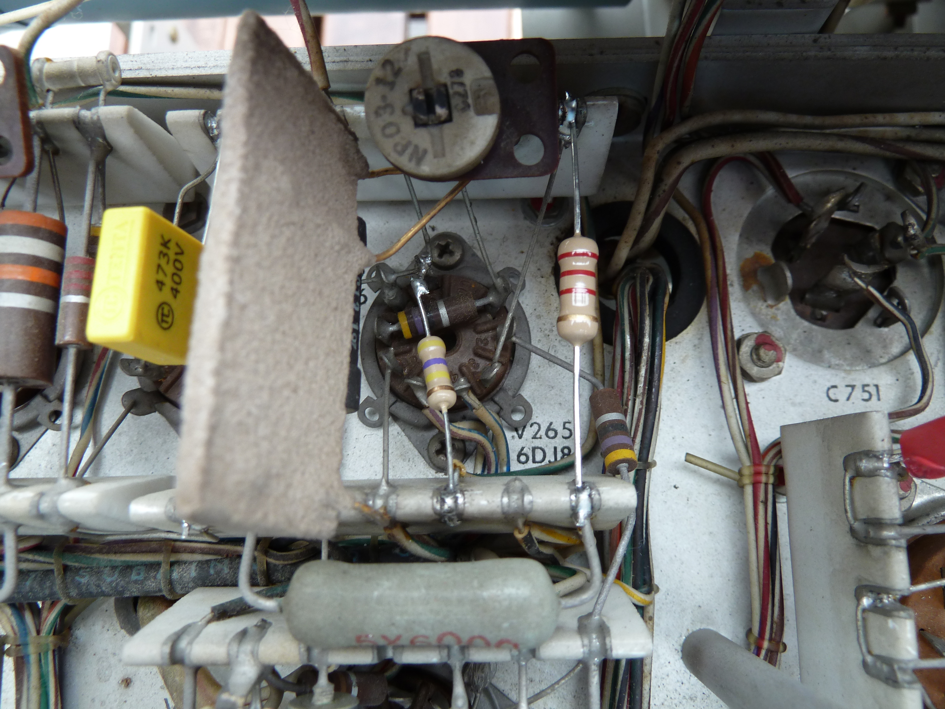
The two resistors that showed resistance values far off the allowed tolerance where replaced by new ones.
After their replacement, the main sweep worked fine and still does.
In order to complete the restauration works, I replaced all remaining paper-based capacitors of the device which turned out to be a lot of work. Often, these caps are very difficult to reach out to and to replace when they are located either under other components or at potentiometer that are behind the faceplate of the oscilloscope.
The final result: Connecting the calibration output to the scope channel input led to the following expected trace:
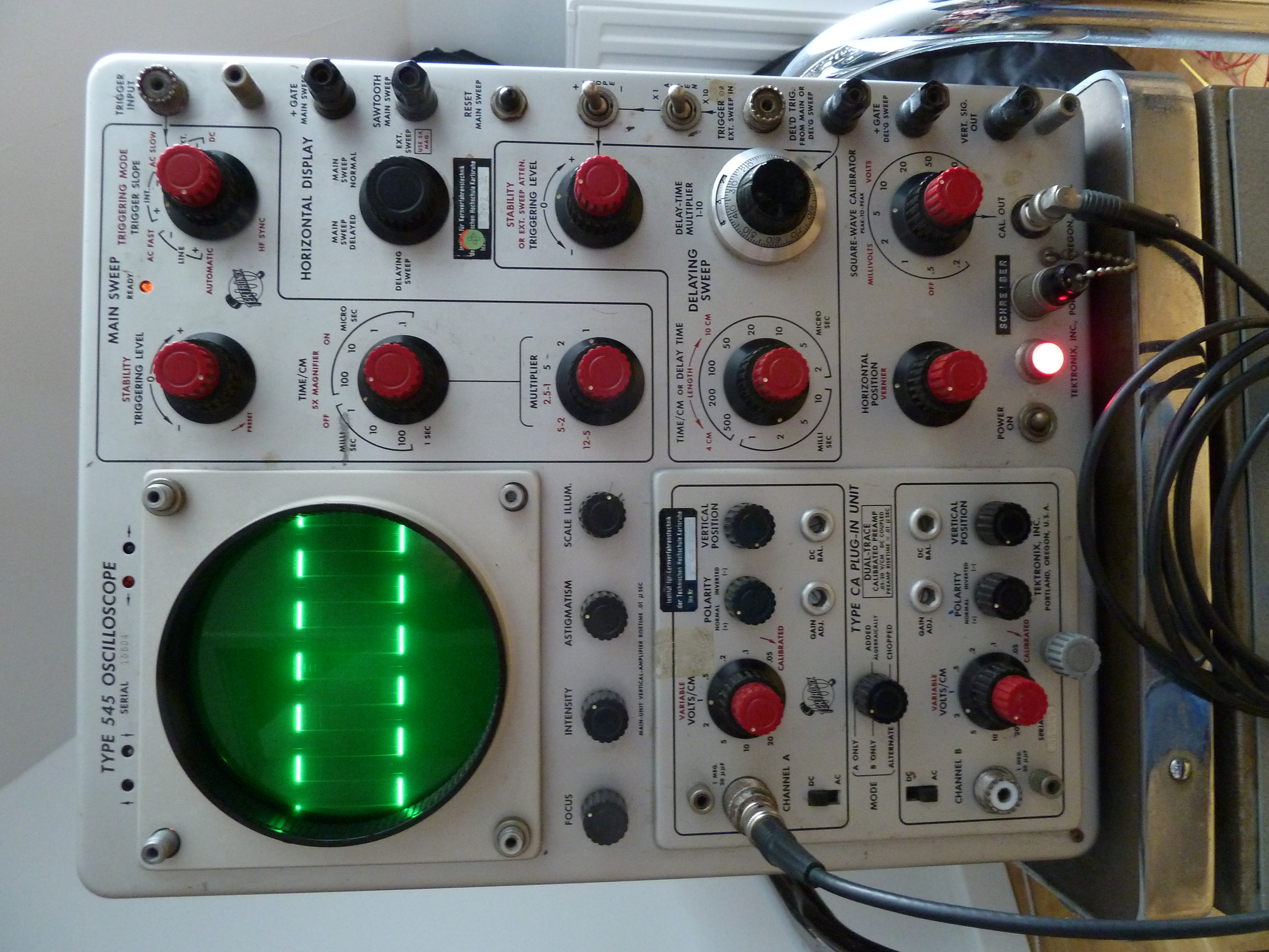
Expected rectangular signal as provided by the calibration circuit. The scope is working fine again!
In summary, with the help of the fantastically written and detailled service manual from Tektronix, fixing this wonderful oscilloscope was not difficult and it is ready to be used when I measurements for low-bandwidth applications are of importance, especially during cold winter days since 500 Watts of energy dissipation really help to heat up my workshop room.